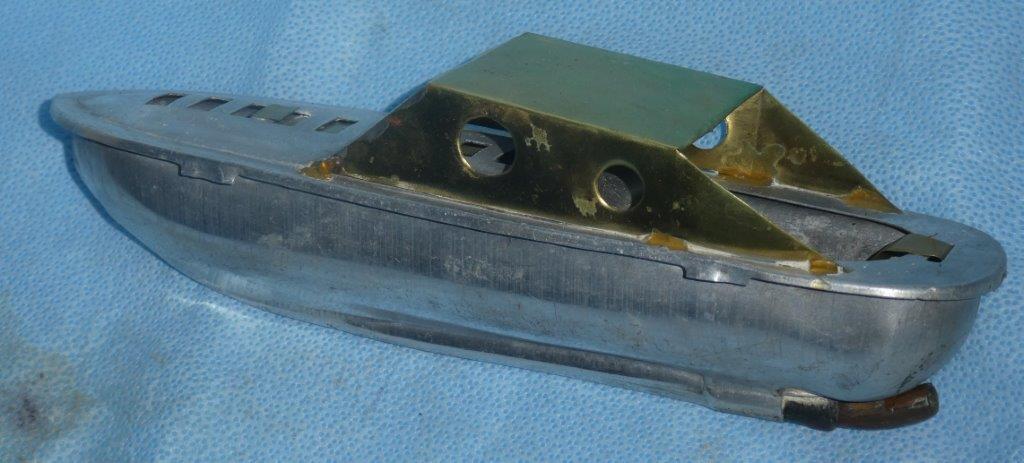
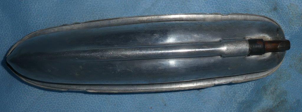
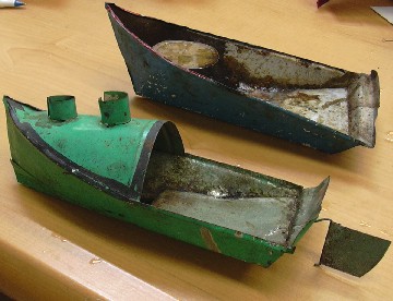
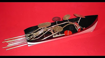
Almost all putt putt boats have 2 outlet pipes, but Rob of Brisbane Australia found a rare, single pipe design. I wondered if filling the boiler could be a problem, but Rob wrote,
“I fill the boiler by inserting a length of small diameter nylex tubing down inside the outlet tube, and then run water into the metal tube. The inner nylex then acts as an air release bleeder tube and the boiler fills up. The first expulsions of water and steam seem to push out whatever is excess, and the remainder commences to pulse in the usual Put-put manner. “
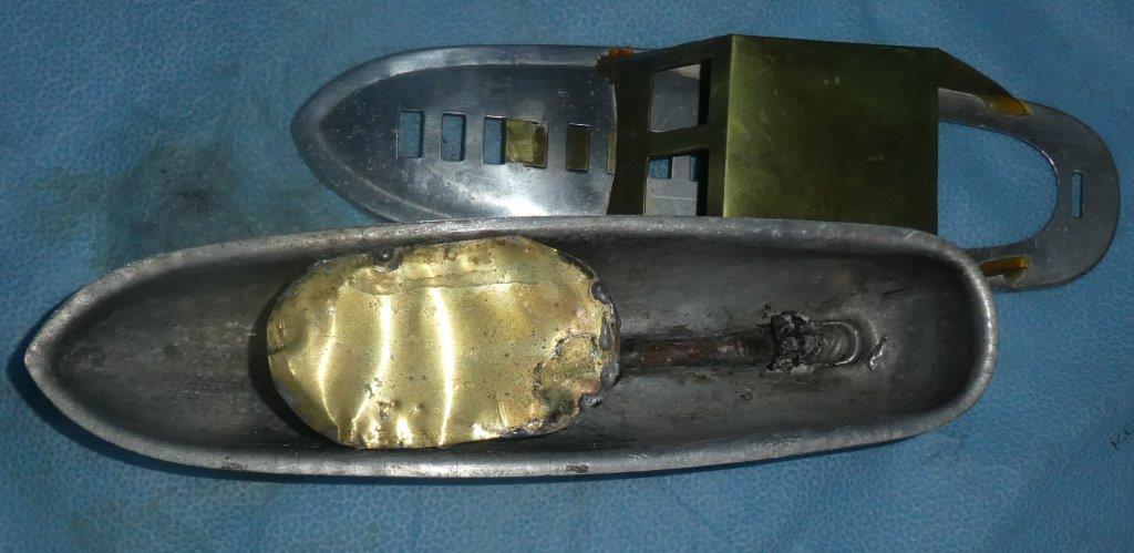
Rob replaced the missing cabin and repaired the leaky boiler. We would both like to know more about singe-pipe pop pops! More about putt putt boats
Though relatively simple construction, putt putt engines ingeniously harness several principles of physics to push the boat and make raucous boat noises.
The advantage of the copper tubing engine is the relative ease of construction, and you cannot wreck it with too much heat. The disadvantage of the coil design is that it is often slower and makes little or no noise.
I'd like to know how this project goes for you. I'm happy to answer questions about it. Feedback from you is an important way for me to know what works and what needs clarification.
The longer I experiment with putt putt boats, the clearer it becomes to me that I have only just scratched the surface. It is too much for one person to conduct all the development and experimentation that needs to be done for this project to reach its full potential. I am happy to have found kindred spirits.
I'd like to know how this project goes for you. I'm happy to answer questions about it. Feedback from you is an important way for me to know what works and what needs clarification.
2 boats from Bangladesh, one uncovered to show the boiler. The bodies are made from old tin cans, which rusted over the decades, causing the dark patches.
Introduction
The first time I saw a putt putt (aka pop pop, Ponyo) boat I couldn't believe my eyes! I must have gotten every science toy known to mankind when I was a kid: rockets, airplanes, slinkys, the bird that dunks its head in water, the junior chemistry set that I almost burned down the house with...I could name dozens. But it wasn't until I was an adult that I encountered a putt putt steam boat. It was chugging away in an outdoor market in Bangladesh-- in Southern Asia-- one of the poorest countries in the world. Made mostly from a recycled milk tin, it sounded like a tugboat and it really zipped fast--all powered by a little vegetable oil lamp. How could such a cool thing have existed without my knowing about it?
Even more astonishing, I learned that putt putt boats (also called pop pop boats) were once very popular throughout the world in the first half of the 20th century. So why did they disappear? I guess tin toys and steam power seemed antiquated after World War II. Batteries and plastics were the exciting thing happening to toys!
Speaking for myself, I'm tired of plastic and batteries, especially in my kid's toys. I must not be alone. Old fashioned toys--including putt-putt boats are becoming popular once again. Science, model and toy catalogs offer stamped tin boats from Asian countries like India, Pakistan and China. You can pick up old ones on eBay.
Part of an entry from a 1933 science magazine.
A word about safety: The boat is surrounded by water and the steam engine cannot explode. Yes, the boats use a candle flame, so of course kids have to be supervised and not touch it. But let's put this in context: We annually challenge our young children to position their faces inches from multiple burning candles stuck into a giant pastry.
About Off-the-Shelf Putt Putt Boat
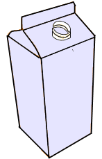
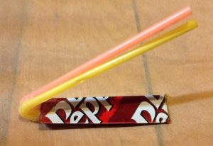
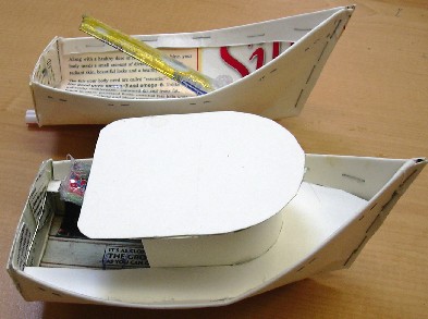
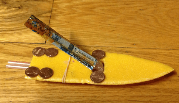
You can make the body of the boat with a recycled, cut-up milk or juice carton, which is easy to cut, water-proof and paintable (although mine are not painted here). Or you make a simpler boat out of a recycled foam grocery tray. In either case the engine is the same, made from a cut-up aluminum soft drink can and drinking straws. The instructions for both the steam engine and the boat are HERE.
Excepting a few experimenters who soldered together engines, putt putt boats have always been something people bought rather than made. Even the boats in Bangladesh required some brass for the engine and solder to seal it. Over the last 15 years I have made hundreds of putt putt boats with one goal in mind: to develop a design such that anybody could make their own. At first I copied engines using brass shim stock, copper tubes and solder. Then I began using epoxy glue instead of solder, and disposable aluminum pie tins instead of brass. After years of slow evolution, I completely redesigned the engine to be made of a cut-up aluminum soda can and flexible plastic drinking straws. Back when I was teaching, almost three hundred of my 8th grade students would make it every year as a technology project.
About Engines
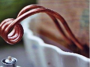
The engine of this boat is simply a coil of copper tubing.
This is the diaphragm type engine I will show you how to make.
I should mention that there are actually two kinds of putt putt boat: the diaphragm kind I concentrate on in this site, and the looped copper tubing kind. Instructions for this design were in the Cub Scout handbooks from 1954 to 1977. The advantage of the copper tubing engine is the relative ease of construction, and you cannot wreck it with too much heat. The disadvantage of the coil design is that it is often slower and makes little or no noise. If you are interested in this type, click here. And here are explanations of how Putt Putt engines work.
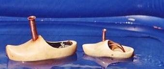
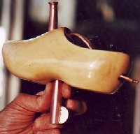
The following detailed information was sent by my good friend from the Netherlands, Dr.Guus Flogel: a retired dentist and professor; and an active artist and experimenter. He makes the most extraordinary Dutch wooden shoe boats, which kept my middle school students mesmerized when he visited my school in January 2006.
On this page, Guus discusses experiments to determine the best size of copper tubing as well as the best shape. In a companion page he describes how to actually make the engines. (Scroll down the document to "Making a Coil Engine")
MATERIAL AND METHODS
I started to build some examples of coil engines according descriptions and drawings I found in hobbyist magazines and on the internet. But the result didn’t satisfy me. So I decided to develop my own engine. This was done by trial and error.
Phase 1:
The engines were made of copper tubes (not brass, which is harder than copper) of respectively 3mm (approx 1/8 inch), 4mm (approx 5/32 inch) and 5 mm (approx 3/16 inch). With each diameter engines of 2, 3 or 4 turns were made. All coil had the same diameter, 12 cm (about ½”). For no good reason only coils with a horizontal axis were tested. Many problems were experienced making coils with the relative small diameter of 12 cm from 5 mm tubes. I had too many failures. My final decision was to stop the tests with them prematurely.
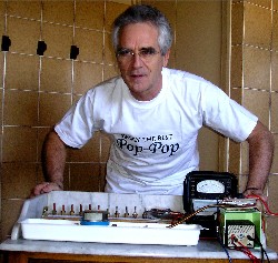
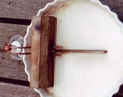
The test were carried out on a simple self made test bench (Picture 1), based on a domestic disc. The water in the disc was about 2 ½ cm height. In case of doubt the water was scattered with little particles like dust for a better visibility of the water flow behind the nozzles. Between the nozzles was a thin separation wall fixed, to make it possible to judge the water flow behind each nozzle separately.
Picture1
Picture 2
The wall was part of a wooden device, made to fix the engines in the desired position. The nozzles were well covered by water (at least 10 mm) over a distance of at least 30 mm. The coil had to extend far enough outside the dish for positioning the burner exactly under it. (Picture 2). The inclination of the engine was as near as possible as it would be in the hull of my boats.
All test was carried out with the same burner, at least for ¾ filled with pure alcohol (nearly 100 %)[Note:In the U.S. the easiest way to buy it is as "Shellac Thinner" where paint supplies are sold]. The wicks were from the same brand and the same thickness. The extending part of the wick outside the burner was each test readjusted at the same length(2mm). Also the distance from the wick to the coil was standardized by a little wire, mounted on the burner to act as a distance holder. In this phase the following variables were involved: the diameter of the tubes and the amount of turns of the coil.
Phase 2:
The test bench was altered a bit to test two engines simultaneously, one engine on each side of the separation wall. Of course for these tests two burners were needed.
As discovered during former tests the amount of heat added to the coil is of distinct influence upon the performance of the engine. All tough identical burners were used this does not exclude variations in heating capacity completely. Therefore, this had to be controlled. First the performance of the two engines was judged after a running time of 8 minutes. Then the two burners were exchanged. If the performance showed not to be influenced, the results were considered legitimate. If not, they were discarded. The burners were readjusted and the tests repeated.
Small alternations of the preceding design were made. Most of them in a region of ca 3-4 cm behind the coils. Because especially in the beginning it was difficult to predict what the effect would be, these alternations were made in two opposite directions. This showed more or less the way to proceed. When finally no more visible improvements could be obtained this part of the study was closed.
Phase 3:
Picture 3
Picture 4
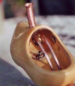
The Engines were mounted in my favourite hull, a wooden shoe. To obtain a fixed position of the burner, a hole was drilled in the bottom of the hull, just beneath the coil. This hole was made ca 10 mm wider than the diameter of the standard used cylinder shaped alcohol tank to give room to a 5 ¼ mm thick silicone liner. This way an aperture was attained just narrow enough to ensure a water tight seal of the alcohol tank and, three-dimentional, a fixed position right under the coil. (picture 4 and 5). Each trial two boats were compared simultaneous.
In this test two different configurations of the tubes between the coil and the nozzles were compared.
a: the tubes were directed all the way from the coil to the stern. The length of the tubes immerged in the water is relatively short.
b: the tubes were going directly downwards from the coil trough the bottom of the hull and from there to the stern. The idea was to get an indication of the importance of the length of the tubes between the coil and the water.
In both boats the total length of the tubes was equal.
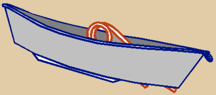
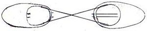
Because it is almost impossible to tune the boats to sail continuous in a straight line, most efforts failed to compare their speed while sailing side by side failed. To compare their performance the example of the old tugboat captains was followed. The boats were connected to each other by two rather short crossing lines (drawing). This way the boats are kept in line when exemplary during pulling.
Just like in phase 2, after 8 minutes of running the burners of the boats were exchanged and the test repeated.
RESULTS
Phase 1:
The engines made of 4 mm outside performed better than those of 3 mm, independent the number of turns of the coils. The performance of the three-turn engines showed better than those with 2 or 4 turns. Therefore only engines with 4 mm tubes and three coils were involved in our further investigations.
Phase 2:
Better then a description the picture shows the final configuration as a result of the comparison of 6 tests. Especially the configuration of the right tube (on the picture) is rather critical.
Phase 3:
Short after the beginning of the trial, boat a seemed to be the looser. But after 5-10 minutes boat b became steadily stronger and finally won this titanic battle.
The result was not as convincing however. When the test was repeated a few hours later and this time boat a and b showed to be equally strong. A third trial didn’t give deviating results.
DISCUSSION AND SUMMARY
-This empiric study was carried out to optimise the performance of the so called coil engines. It is the most primitive way of investigating. Sometimes results can be obtained but this is limited to the fact that the method doesn’t give any insight were the effects come from and why. Besides we didn’t have an accurate measuring method. To make further progress more basic work has to be done. In this regard we have to realise ad keep in mind the relative (economic) importance of the project. This makes we have to limit our work to simple and inexpensive methods. Jeff Bindon made a good start with his look-through engine. Perhaps it makes sense to repeat his approach for coil engines with replicas made of quartz glass.
-three coil engines made from tubes with 4 mm diameter outside performed the best in this study.
-The goal of phase 3 test was so examine the influence of the length of the tubes between the coil and the water upon the performance.
The problem was, for making variant b (see material and method) the introduction of a third variable was unavoidable: the tubes needed two bends of about 90 degrees. However the bends were relative soft, it is plausible this increases the resistance for the water flow. After all, this makes it impossible to draw conclusions concerning our initial premise
- Most pop-pop boats with boiler type engines are build as light as possible. Their weight is approx. 30-35 gr. Compared to this the “steamshoes” in this investigation are extremely heavy, approx 195 gr. In spite of that, their performance is surprising. This may due to the fact that boiler-type engines are spending a part of their energy by moving the membrane of the boiler (several hundreds/minute) instead of using it for moving the vessel.
One of the biggest hassles has been finding the right size of tubing. Bob Jay seems to have solved the problem for people who have a PepBoys (automotive store) nearby. As he wrote me,
"Here's the skinny on the copper tubing . At two local Pep Boys there is a large section of an isle dedicated to various auto parts called " HELP ". They are on red cardboard with the part in plastic blister heat shrink. The red pack has the word " HELP!" in white letters. The tubing that I used is 1/8" x 8'. The HELP number is 55134 and the SKU # 37495 55134 2. I hope this helps ya out."
Thanks Bob. Another thing I think is worth pointing out is that copper can be annealed (softened). This is important because bending hard tube results in kinks (which block the tube) rather than smooth bends. Strangely, copper is softened in exactly the way that steel is hardened--by heating to red hot and quickly quenching in water. As copper is worked (bent, for instance) it once more starts to harden. It might have to be annealed again. The procedure is explained in both Marc and Guus' articles.
Though relatively simple construction (no moving parts, unless you count the deflection of the bottom of the boiler), putt putt engines ingeniously harness several principles of physics to push the boat and make raucous boat noises. And instead of just ejecting the water until the boiler is dry--as intuition seems to tell us it should be-- the water keeps coming back in a continuously repeating cycle. Understanding the cycle uses all of Newton's laws of motion.
Tip 1: Water expands a lot when it turns to steam.
Most people know this, but did you know steam can occupy more than a thousand times more volume than the water it came from? If it is prevented from expanding, it builds up pressure instead. That's what happens with popcorn, which ideally has a 14% moisture content inside. The hard shell keeps the bit of moisture contained. The steam pressure builds until the kernel explodes. If it has dried out to 9% moisture, you can hardly pop it. Interestingly, putt putt boats are sometimes called "pop pop" boats.
Both popcorn and the putt putt engines employ violent expansions of steam, yet both are pretty safe because such a small amount of water is involved. Don't ever try to bake an unopened coconut in the oven, though!
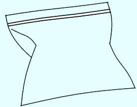
If you put a spoonful or two of water in a ziplock bag (or any plastic bag that can be sealed) and heat it in a microwave oven, you can see how the steam occupies many times more volume than the water it came from. It can't explode because the plastic becomes so soft it can't contain any pressure. Balloons with bit of water and tied also work.
Phase 1: Explosive, expansion.
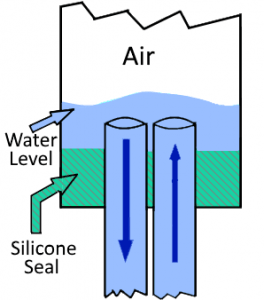
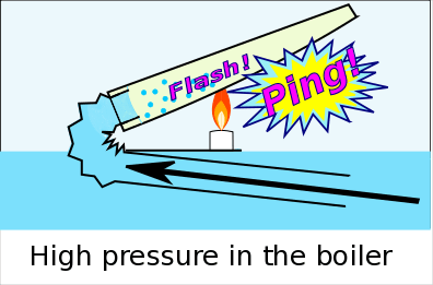
The aluminum boiler does not fill full with water.
Let's first establish that the aluminum boiler does not fill full with water. Tilting the boiler to prime it makes the boiler stand up in such a way as to fill the straws and just a bit of the bottom of the boiler. If you had x-ray vision, you would see that when you prime the engine with water, the water comes in one straw and runs back out the other straw without putting much water in the aluminum boiler. This is as it should be. The "wetting" step deposited tiny droplets of water on the inside walls of the boiler. Once the aluminum is heated, even the tiny candle can flash boil those small droplets of water almost instantly, and they expand enough to run the engine.
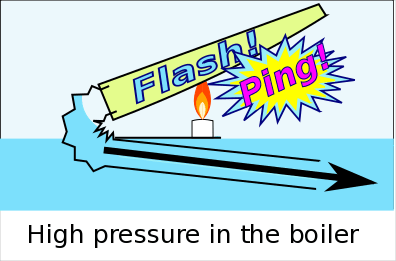
Two things happen as the droplets flash explosively into steam: The bottom of the boiler pushes out with a ping. And the the water in the straws is pushed out.
If you measured the pressure inside the boiler, it would be higher than atmospheric pressure
Tip #2: A moving water column has momentum.
Sir Isaac Newton's First Law of Motion states that things in motion tend to stay in motion until something stops them. Even if you turn off the engine of a moving train, momentum alone can keep it going for miles.
A moving column of water in a pipe also has momentum, just like a train. When a column of water is suddenly stopped --as when someone closes a valve abruptly-- the momentum of the water is transferred to the plumbing. It can make noise or even tear plumbing loose. Hydraulic engineers and plumbers call this phenomenon"water hammer". It was more common on older plumbing before fixtures were designed to minimize it.
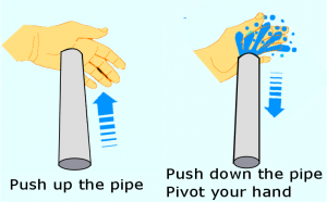
You can make a crude water pump that works because of the momentum of a water column. You need only your hands and a pipe. The pipe can be any diameter that you can seal one end of with the palm of your hand and it can't have holes or cracks in it. I have used the rigid metal extension of a vacuum cleaner that connects the flexible hose with the inlet attachment. A cheap PVC pipe around 1" or so is perfect. It should be at least a few feet long.
With at least 2 feet of the bottom of the pipe in water, cover and seal the top opening with the palm of your hand. Quickly jerk the pipe up. With the top sealed, the water in the pipe will lift up with the pipe. After the pipe has gone up a foot or so, jerk the pipe back down, while at the same time pivoting your hand to open up the top.
Back to the steam engine, the fast-moving water columns in the straws has momentum. That momentum tends to make the water want to charge ahead even when the boiler is no longer pushing it. That's good! It gives the engines an instability that keeps the cycles repeating over and over.
Tip 3: When steam condenses, it leaves a void.
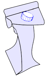
I know this sort of an obvious corollary of tip #1, but when most people think of condensation, they think of water droplets on the glass of an iced drink. The following demonstration is far more dramatic. Take one of those 1/2 gallon orange juice cartons with the screw-on lid and put a small amount of water (1/2" inch at the bottom, or several tablespoons). Put the carton in a microwave oven (you'll probably have to put it on its side) but do not put the lid on yet!!! If you put the lid on tightly now, the carton will explode. Set the power on high. The idea is to get the water inside boiling, then keep it boiling for about a minute. When it has--carefully so you don't get burned--take the carton out of the microwave and screw the lid on all the way.
The carton is now filled with steam. You can just let it condense slowly, but it's really dramatic if you spray the carton with cold water. Atmospheric pressure--about 14 pounds per square inch--easily crushes the carton.
Phase 2: Rarified, momentous expansion.
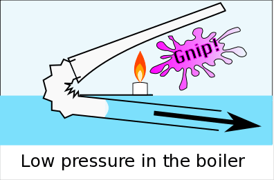
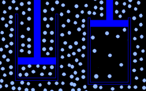
Although the water is still jetting out the ends of the straws because of momentum, the situation inside the boiler is very different from phase 1. The boiler is dry, no longer generating steam pressure because the water droplets have boiled off into steam. The column of water in the straws is no longer being pushed. But the momentum of the exiting water in the pipes keeps it going outward. Behind it --inside the boiler-- it expands the amount of volume available to the fixed amount of air inside. This creates a lower-than-atmospheric pressure inside the boiler. Colloquially, people call this a "vacuum", which isn't really right because there is still air in there, just less of it. "Rarified atmosphere" is a better term, I think. Whatever you call it, it's a huge change from phase 1, when there was high pressure in the boiler!
Normal (left) and Rarefied(right) Atmosphere
The bottom of the boiler bulges inward (concave), again making a sound (I called it "gnip" ('ping" spelled backward) in the illustration).
Phase 3: Spring-back contraction.
We could say that the suction inside the boiler is now trying to pull the water column in the straws back into the boiler. More accurately, we should say say that normal atmospheric pressure is pushing the water back in. In any case, the water's momentum has been pushing against the air pressure. When the water's momentum is finally gone, the air pressure springs it back toward the engine. Some of the water squirts back into the aluminum boiler. Remember, that boiler was dry in phase 2. The candle has still been heating the metal, though, so the droplets of water explode into steam. There is high steam pressure in the boiler, again pushing out the water, and so on. The cycle repeats several times per second until the candle burns out.
Lingering question 1:
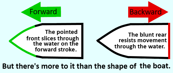
Why doesn't the boat go backward in reaction to the water column returning toward the engine?
Sir Isaac Newton's Third Law of Motion is the familiar, "For every action there is an equal and opposite reaction." This is what propels jets and rockets--even in the deep vacuum of space. So, when the water jets backward out of the straws (action) the boat jumps forward (reaction). OK so far. But then the water rushes back into the straws, which would suggest the boat should actually kick backward in reaction. Why doesn't the putt putt boat just shake forward and backward in the water and not really go anywhere?
For years I assumed the whole answer lay in the shape of the boat. The pointed front cut forward through the water, while the blunt square back of the boat resisted going backward, sort of a hydraulic ratchet. But when I actually put it to the test--mounting engines on square boats, or even backward on pointed boats-- the engine still chugged forward. Clearly, some other principle is at work here.
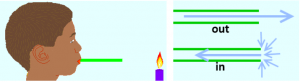
I am speculating that the answer lies in the different way the water exits and enters the ends of the straws. Consider this: If you blow through a straw, you can blow out a candle from more than a foot away. But if you suck in the air, you have to be within an inch or two of the flame to blow it out (I am not suggesting you breath fire to try this out). This leads me to think that in the first case, much of the air keeps going straight when blown out. But in the second case, air enters the straw from all angles --not just in front. If we then apply Newton's Third Law, most of the reactions cancel each other out in the second case.
However, Dr. Jeff Bindon explains it another way, and I am unable to find a flaw in his reasoning. He uses this analogy to illustrate why sucking water into the engine does not cancel out the expulsion phase:
Imagine a man standing at the front of the flat deck of a small boat. He starts to run across the deck towards the back and as he accelerates, he exerts a force on the deck and the boat is propelled forwards. He continues to accelerate and exert a force until he comes to the end of the deck and leaps into the water. The boat is now moving and as it does so, it passes another man in the water and he grabs hold of the ladder at the back of the boat. The boat jerks him into motion and the boat is slowed slightly. He climbs onto the deck and proceeds to accelerate and run towards the front of the boat. He exerts a force on the deck and the boat is retarded. But he does not want to leap off the front of the boat so he decelerates and exerts a propulsive force on the deck. By the time he has stopped, the propulsive force he has exerted is exactly equal to the retarding force he initially exerted. Or you can argue that he walks slowly to the front of the boat and exerts no force when he starts or stops. So, a series of men floating in the water, climbing on board, running and jumping back into the water can propel a boat !!
Lingering question 2:
Why doesn't the glue sealing the engine burn?
Although the putt putt engine is the most challenging project on this site, it would be even harder if you had to solder it together, as is the traditional way to make them. Furthermore, most solder does not stick to aluminum, so you would have to find special brass sheets instead.
It is not a good idea to run the engine dry, but when water is in, it stays below the temperature that would damage the epoxy and silicone. Consider that a water balloon can be held above a lit candle without bursting. The water keeps the rubber cool.
Note: This article was originally published in March 2005
In addition to old patents, there is more recent technical information toward the bottom of this page.
Mr. Joel Rosenberg--whom we can all thank for finding and making these patents available as PDF documents--works with Boston's Museum of Science. He and others are developing a wide-ranging high school engineering program called Engineering the Future that includes students making putt putt boats.
The patents are in the public domain. I have added some commentary along with the links.
Thomas Piot's 1891 patent(PDF here) started it all. As he says, "My said invention is especially useful in the case of toy boats..." We can only guess about how he first came up with the idea. Did he observe something that led him serendipitously to the invention? The first two pages demonstrate a strong sense of science, so whatever triggered it, the development was still no easy accident. The third page shows pictures.
Those of us who have struggled to make putt putt engines--knowing it is possible--stand in awe of this man who made them without seeing somebody else's design! We stand on the shoulders of giants, but occasionally lightning strikes and someone invents something completely new. Let us pay our respects to Thomas Piot! Here is the best page I know of with biographical information about Désirée Thomas Piot.
Charles McHugh's 1915 patent(PDF) which was the first step to another patent of his 11 years later (see below). McHugh discovers that, "In some cases, if the boiler top is quite thin, a sound producer is provided for creating an interesting illusion.." He has discovered that by incorporating a diaphragm into the boiler he creates that wonderful sound that adds so much to the putt putt experience!
William Purcell's 1920 patent(PDF) appears to be the start of the other kind of putt putt boat: a boiler of coiled tubing. This kind of engine is very simple and durable. For years it was the only do-it-yourself putt putt engine. However, it does not make as much sound or go as fast as the diaphragm kind. Purcel realized it might be most practical to power toy boats with it, but the patent seems to leave open the possibility that it might be scaled up for a big boat. His sentiments are echoed in virtually all my classes, where someone will express an interest in a giant putt putt engine to power a full-size boat.
Charles McHugh's 1926 patent(PDF) further developed the engine to commercially viable design that could be produced in quantity. Notice how 9 years later the whole design is actually somewhat simpler. From the text and illustrations we can appreciate all the work that Charles McHugh and his partner Durward Williams devoted to making the engine what it is today. When I have some time, I would love to research how their company did.
Paul Jones' 1935 patent really emphasizes the mass-production using various stamp presses. The pressed-together parts seem to be more durable--less dependent on solder not melting. I have a Paul Jones boat in a balsa wood hull that still works well.
Interestingly, on page two Jones describes the top and bottom of the engine as "...having a different co-efficient of expansion and contraction..." Thermostats at that time were made of "bimetallic strips," which were strips of two metals stuck together. As the strips got hotter, the metals would expand at different rates, which caused the unit to bend (completing an electrical circuit). I think my all-aluminum boiler shows that it is hydraulics that make the engine work, not different rates of expansion of metals.
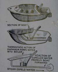
Another interesting thing is the timing of the patent application: 1934. The illustration on the right is from a science publication of 1933 featuring a toy boat manufactured and imported from Japan. You can see a PDF file of the whole page here. The text which accompanies the illustration has the same incorrect assumption about variable bimetallic expansion making it work. That and a very similar-looking engine make me wonder how much the Japanese design influenced the Paul Jones patent.
Mr. Rosenberg also uncovered some very technical articles for engineers about putt putt boats, including such topics as scaling the engines larger. I cannot post these on the web because of copyright. If you contact me I can direct you toward them.


 Most people know this, but did you know steam can occupy more than a thousand times more volume than the water it came from? If it is prevented from expanding, it builds up pressure instead. That's what happens with popcorn, which ideally has a 14% moisture content inside. The hard shell keeps the bit of moisture contained. The steam pressure builds until the kernel explodes. If it has dried out to 9% moisture, you can hardly pop it. Interestingly, putt putt boats are sometimes called "pop pop" boats.