MATERIAL AND METHODS
I started to build some examples of coil engines according descriptions and drawings I found in hobbyist magazines and on the internet. But the result didn’t satisfy me. So I decided to develop my own engine. This was done by trial and error.
Phase 1:
The engines were made of copper tubes (not brass, which is harder than copper) of respectively 3mm (approx 1/8 inch), 4mm (approx 5/32 inch) and 5 mm (approx 3/16 inch). With each diameter engines of 2, 3 or 4 turns were made. All coil had the same diameter, 12 cm (about ½”). For no good reason only coils with a horizontal axis were tested. Many problems were experienced making coils with the relative small diameter of 12 cm from 5 mm tubes. I had too many failures. My final decision was to stop the tests with them prematurely.
The test were carried out on a simple self made test bench (Picture 1), based on a domestic disc. The water in the disc was about 2 ½ cm height. In case of doubt the water was scattered with little particles like dust for a better visibility of the water flow behind the nozzles. Between the nozzles was a thin separation wall fixed, to make it possible to judge the water flow behind each nozzle separately.
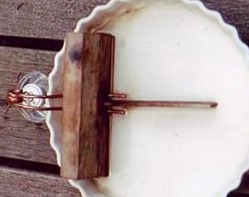
The wall was part of a wooden device, made to fix the engines in the desired position. The nozzles were well covered by water (at least 10 mm) over a distance of at least 30 mm. The coil had to extend far enough outside the dish for positioning the burner exactly under it. (Picture 2). The inclination of the engine was as near as possible as it would be in the hull of my boats.
All test was carried out with the same burner, at least for ¾ filled with pure alcohol (nearly 100 %)[Note:In the U.S. the easiest way to buy it is as "Shellac Thinner" where paint supplies are sold]. The wicks were from the same brand and the same thickness. The extending part of the wick outside the burner was each test readjusted at the same length(2mm). Also the distance from the wick to the coil was standardized by a little wire, mounted on the burner to act as a distance holder. In this phase the following variables were involved: the diameter of the tubes and the amount of turns of the coil.
Phase 2:
The test bench was altered a bit to test two engines simultaneously, one engine on each side of the separation wall. Of course for these tests two burners were needed.
As discovered during former tests the amount of heat added to the coil is of distinct influence upon the performance of the engine. All tough identical burners were used this does not exclude variations in heating capacity completely. Therefore, this had to be controlled. First the performance of the two engines was judged after a running time of 8 minutes. Then the two burners were exchanged. If the performance showed not to be influenced, the results were considered legitimate. If not, they were discarded. The burners were readjusted and the tests repeated.
Small alternations of the preceding design were made. Most of them in a region of ca 3-4 cm behind the coils. Because especially in the beginning it was difficult to predict what the effect would be, these alternations were made in two opposite directions. This showed more or less the way to proceed. When finally no more visible improvements could be obtained this part of the study was closed.
Phase 3:
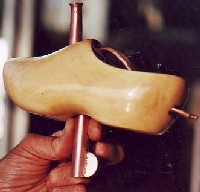
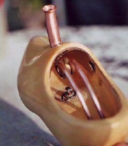
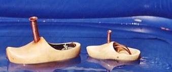
The Engines were mounted in my favourite hull, a wooden shoe. To obtain a fixed position of the burner, a hole was drilled in the bottom of the hull, just beneath the coil. This hole was made ca 10 mm wider than the diameter of the standard used cylinder shaped alcohol tank to give room to a 5 ¼ mm thick silicone liner. This way an aperture was attained just narrow enough to ensure a water tight seal of the alcohol tank and, three-dimentional, a fixed position right under the coil. (picture 4 and 5). Each trial two boats were compared simultaneous.
In this test two different configurations of the tubes between the coil and the nozzles were compared.
a: the tubes were directed all the way from the coil to the stern. The length of the tubes immerged in the water is relatively short.
b: the tubes were going directly downwards from the coil trough the bottom of the hull and from there to the stern. The idea was to get an indication of the importance of the length of the tubes between the coil and the water.
In both boats the total length of the tubes was equal.
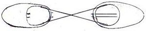
Because it is almost impossible to tune the boats to sail continuous in a straight line, most efforts failed to compare their speed while sailing side by side failed. To compare their performance the example of the old tugboat captains was followed. The boats were connected to each other by two rather short crossing lines (drawing). This way the boats are kept in line when exemplary during pulling.
Just like in phase 2, after 8 minutes of running the burners of the boats were exchanged and the test repeated.
RESULTS
Phase 1:
The engines made of 4 mm outside performed better than those of 3 mm, independent the number of turns of the coils. The performance of the three-turn engines showed better than those with 2 or 4 turns. Therefore only engines with 4 mm tubes and three coils were involved in our further investigations.
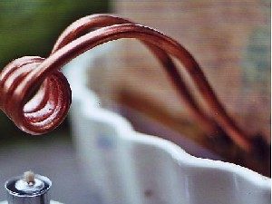
Phase 2:
Better then a description the picture shows the final configuration as a result of the comparison of 6 tests. Especially the configuration of the right tube (on the picture) is rather critical.
Phase 3:
Short after the beginning of the trial, boat a seemed to be the looser. But after 5-10 minutes boat b became steadily stronger and finally won this titanic battle.
The result was not as convincing however. When the test was repeated a few hours later and this time boat a and b showed to be equally strong. A third trial didn’t give deviating results.
DISCUSSION AND SUMMARY
-This empiric study was carried out to optimise the performance of the so called coil engines. It is the most primitive way of investigating. Sometimes results can be obtained but this is limited to the fact that the method doesn’t give any insight were the effects come from and why. Besides we didn’t have an accurate measuring method. To make further progress more basic work has to be done. In this regard we have to realise ad keep in mind the relative (economic) importance of the project. This makes we have to limit our work to simple and inexpensive methods. Jeff Bindon made a good start with his look-through engine. Perhaps it makes sense to repeat his approach for coil engines with replicas made of quartz glass.
-three coil engines made from tubes with 4 mm diameter outside performed the best in this study.
-The goal of phase 3 test was so examine the influence of the length of the tubes between the coil and the water upon the performance.
The problem was, for making variant b (see material and method) the introduction of a third variable was unavoidable: the tubes needed two bends of about 90 degrees. However the bends were relative soft, it is plausible this increases the resistance for the water flow. After all, this makes it impossible to draw conclusions concerning our initial premise
- Most pop-pop boats with boiler type engines are build as light as possible. Their weight is approx. 30-35 gr. Compared to this the “steamshoes” in this investigation are extremely heavy, approx 195 gr. In spite of that, their performance is surprising. This may due to the fact that boiler-type engines are spending a part of their energy by moving the membrane of the boiler (several hundreds/minute) instead of using it for moving the vessel.