What You Need
I used to get parts from kelvin.com when I was teaching. I am providing their catalog ordering numbers and links in case you are interested. Nowadays you can probably find less expensive versions elsewhere online.
Note: These are November 2020 prices
- PDF Pattern and the map of the project
Some browsers and PDF viewers change the scale and distort the pattern size. Choose the print options that say something like "Actual Size" or "Scale: 100%." - 2N3904 Transistor (any small signal NPN transistor will work for the 2N3904)
$0.25
Stock #: 630117
Buy 10 - 99 $0.20 each
Buy 100 or above $0.15 each
http://kelvin.com/2n3904-transistor/ - 2N3906 Transistor
Price: $0.25 Stock #: 630119
Buy 10 - 99 $0.20 each
Buy 100 or above $0.15 each
http://kelvin.com/2n3906-transistor/ - 4.7K ohm (#010095) and 82K Ohm, 1/4 Watt Resistor (#010138)
Price: $6.00 each
Stock #s: 010095 and 010138
200 / pkg. - 0.01 uf (or 0.01 mfd - they are both microFarad) ceramic disk capacitor - Kelvin does not carry these anymore, but you can buy them in bulk from Amazon and other online stores. If you still want to buy from Kelvin, you can get 0.01 mfd monolithic capacitor instead. The downside of a monolithic capacitor is that you need to handle it more carefully.
- 8 ohm 2 inches Round Speaker
Price: $0.85
Stock #: 350009
Buy 4 or above $0.75 each
http://kelvin.com/round-speaker-2-in/ - 9V Battery Snap
Price: $0.25
Stock #: 220017
Buy 100 or above $0.19 each
Minimum order of 10 required.
http://kelvin.com/9v-battery-snap-i-shape/ - #22 (or 22 gauge, 22 AWG) solid (not stranded) wire. It should be insulated, not bare wire. (If you want to buy it somewhere else, you can do a search for " 22 AWG insulated solid copper wire." If that doesn't work, try "22 AWG solid hookup wire." Or it might be available at hardware, building centers or model train supply places.)
Price: $9.95 for 100 feet
Stock #: 330193 for red, comes in other colors.
Buy 3 or above $8.95 each
Kelvin says: "Copper prices are currently fluctuating. Copper wire prices are subject to change at time of order. We will notify you if there is more than a 10% increase in price.
http://kelvin.com/22-solid-wire-red/ - 100% silicone caulk
People usually get it in 10 ounce cartridges from discount stores or hardware stores for about 5 - 6 dollars which will make dozens of projects. Putting a nail in the tip keeps it from drying out. Make sure it's 100% silicone and clear. - Clear, flexible plastic sheet.
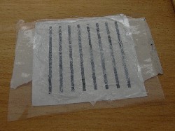
This will form the base for the circuit board. It could be builder's polyethylene vapor barrier if it's clear enough to see through it, at least when that something is close. You could use the plastic from the large, thicker zip-lock freezer bags (not the flimsy sandwich ones). I used to use a heavy (but still very flexible) clear storm window plastic sheet that I could buy by the foot at the hardware store, shown in the picture. Actually, you can't see it because it's transparent, but you can see the paper it's wrapped with. - Soldering Iron
Price: $4.95
Stock #: 990098
Buy 6 or above $4.65 each
http://kelvin.com/economical-soldering-iron-2-prong/ - Electrical (not plumbing) solder, 1/32 in. dia. (1/16 is ok, although 1/32 is easier to use)
All hardware stores have electrical solder. DO NOT use plumbing solder. Kids should never put solder into their mouth (especially if the solder wire contains lead) and they should wash their hands after handling it. I use lead-free solder although it's a little harder to solder. - Thin cardboard to spread silicone, masking tape, thumb tack, sandpaper, scissors, inexpensive wire stripper.
Step 1 Cut, tape pattern to plastic
Print out this PDF page with the pattern and the map of the project. Some browsers and PDF viewers change the scale and distort the pattern size. Choose the print options that say something like "Actual Size" or "Scale: 100%."
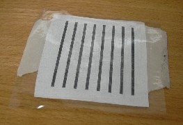
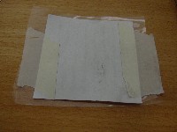
This picture on the left shows the plastic on top (hard to see), the pattern under it (print side to the plastic) and, finally, two pieces of masking tape sticking the pattern to the plastic. Some tape is hidden by the paper. Right is the other side.
I first cut the clear, fexible plastic to long 3" strips. Each of my students then cut off one 3" square of it. Then they also cut out a pattern (it's in the corner of the PDF page you just printed out). Next they tape the smaller pattern to the plastic so the print side is facing the plastic. We use masking tape. Do not fold the tape over if it goes past the edge of the plastic. Trim it, or just let it hang over.
Step 2 Spread silicone
- Use some sandpaper to scuff the plastic, at least where the white of the pattern is. This is so the silicone will stick, not peel off.
- This is a good time for students to write their initials on the plastic so there aren't mix-ups.
- Next squeeze a serpentine line of silicone on the scuffed plastic, as shown in the picture.
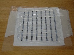
- Finally, use a piece of cardboard to spread it out as smoothly as possible over the white part.
Step 3 Strip, cut, glue wires on
- Strip the insulation off of about 18" of the 22 guage wire. A cheap wire stripper makes it easier than using a razor blade. We strip a few inches at a time.
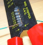
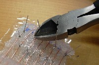
- Straighten the wire as much as possible, then cut it into 2" pieces, 8 of them.
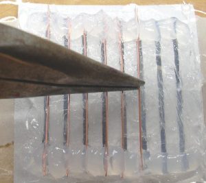
- After the spread out silicone is at least "skinned over", deposit two more lines of silicone near the ends of the pattern lines, perpendicular to them.
- Then push the ends of the wire into the silicone, right over the pattern lines. Pliers might help here. If the 2 inch wires are not straight they will cross and short circuit, ruining the project.
Step 4 Place, Solder the Components in
- Now that the bare, 2 inch-long wires are glued in, you can remove the pattern and tape.
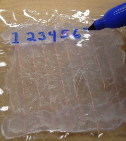
- It's a lot easier to get the electrical components in the right place if you number the wires. A "Sharpie" type (thin) permanent marker works best. Writing on the plastic side (not the silicone and wire side) at the top of the wires--starting on the left--label the wires from one to eight.
- I put the transistors in first. Punch holes with a thumb tack, remembering three things.
-
- First, the transistors are right in the middle--not near either end of the wires.
- Second, make sure you are punching wires 2, 3 and 4 for the 3906 transistor, and 5,6 and 7 for the 3904 transistor.
- Finally, although it does not matter if you punch the hole just to the left of the wire, or just to the right of it, it does matter that you punch it very close to the bare wire. The leads from the transistors must touch the orange copper wires, or they will be hard to solder.
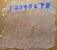 The places to punch the 6 holes for the 2 transistors are shown above in red.
 -
- Before you put in the transistors, you will need to bend the outside wires.
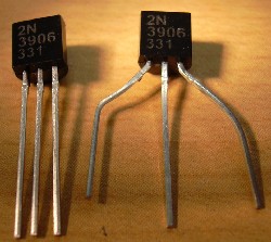
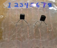
First spread them outward at about a 45 degree angle, then bend "elbows" so the ends are going in the original direction. When the outside leads are spread out like a pitchfork, they will able to reach the 3 wires they will straddle. - Push the transistor leads through. Notice that the transistor stays on the plastic side (left picture below), while the leads go through to the silicone and wire side (right picture).
I give my students some tips for soldering success.
- Make sure the lead from the transistor and orange copper wire to be soldered are touching each other.
- Breifly wipe the crud off the tip of the soldering iron on a moist sponge.
- Melt a little solder onto the connection, then do not add more solder. But do rub the connection with the hot tip of the soldering iron. Rubbing seems to make the solder flow into the connection better.
- When the transistor has cooled a little, do the wiggle test. Sometimes it looks like a connection is soldered, but wiggling the transistor can show if one or more leads are not really glued.
- You should cut off the extra lead wire sticking out beyond the solder connection because it might bend over and short out with another wire.
- Put in and solder the rest of the components. Do not punch holes where the 8 wires are glued to the circuit board (the first time you used the silicone, to hold the ends of the wires), because the silicone covering them will make it impossible to solder there.
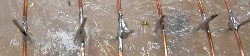
- You will need two pieces of wire which are as long as your pinky finger--stripped at each end-- to connect the speaker to the project.
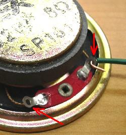
- The red arrows point to the the two solder tabs (with holes) that you will solder onto.
- The upper solder tab shows the stripped end of a wire hooked through, ready to solder.
- When soldering the speaker tabs, sometimes the magnet in the speaker attracts the tip of the soldering iron. The way to minimize the attraction is to keep the tip of the soldering iron pointed toward the speaker.
- You might see a plus+ and minus- next to the solder tabs, but it does not matter which lead goes into wire 4 and which goes into 5.
- While you are cutting the two wires for the speaker, cut another short piece of wire and strip the ends for the jumper wire that connects wire 3 with wire 7.
- When you are ready to put in the battery snap, be careful that the black lead goes to wire 5 and the red lead goes to wire 2.
- When you are done soldering, cut off all the leads sticking out past the solder connection. Also make sure that no wires on top are crossing. For example, the capacitor has long, bare lead wires; make sure that they do not touch the resistor leads or transistor leads.
- Double check to make sure all the component leads go to the right wires. Common mistakes include mixing up the 3904 transistor with the 3906, flat side of one or both of the transistors facing the wrong way, mixing up the resistors, and (especially) bad solder connections that look soldered but are not (remember the wiggle test).
- I use a technique to test the projects the first time with a battery that does not burn out the transistors if something is wrong.
- The student holds onto the touch wires while I touch the battery to the battery clip for less than a second.
- If we don't hear a beep from the project right away, we know something is wrong.
Leaving the battery on longer can burn out transistors very quickly if a component is in wrong, or there is a short circuit.
Sometimes students hook up the battery before I've checked it, with some mistake in the wiring or crossing wires, and it destroys one of the transistors. Then they have to unsolder the transistor and put a new one in.
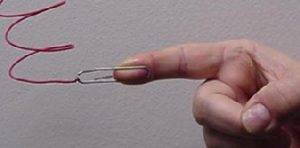 I mentioned in the introduction that you can cheat by squeezing the touch wires harder or softer. Mr. Bird came up with the variation of soldering the touch wires to paper clips to maintain a constant pressure. Another variation is to solder the touch wires to pennies, then hold the pennies to the skin with rubber bands.